Previous Quizzes
Winner of the Quiz
damien goulmot
SYSTRA IBT
Incremental Launch Quiz Series
05 - 11 Feb 2026
Week 11 – Cantilever Deflection at Maximum Launch
Estimated Time: 6–7 min | PDH/CPD: 1.0 hr | Difficulty: Advanced
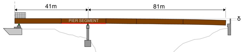
Background: The Sombrio bridge is a two-span composite steel plate girder bridge (40 m + 82 m) launched across a deep ravine in Port Renfrew, BC. Four plate girders were incrementally launched without a temporary pier or launch nose, using precast deck panels as tail counterweight, thickened pier-segment bottom flanges, and crane-assisted final lift. (Parameters simplified for conceptual learning. Allow +25% for cross-frames, connection & splice plates. Girders launched without formwork; ignore wind.)
Engineer's Mind: At maximum launch (81 m cantilever, 41 m tail), estimate downward tip deflection—critical for crane lift planning and bearing alignment. The system acts as single span beam overhanging one support with uniformly distributed load. Using standard beam deflection formula accounts for restraining effect of back span on cantilever deflection.
Question: During this launch stage, the fully spliced and connected girders reach maximum cantilever. The girders are supported on roller supports at the abutment and pier. Estimate the downward tip deflection of the 81 m cantilever. Given:
- Single span beam overhanging one support cantilever deflection: δ = w/(6EI) × [3a²b + 3ab² + b³]
- a = 81m and b = 41m
- w = 7.13 kN/m per girder (incl. secondary steel)
- E = 200 GPa
- Strong Axis Moment of Inertia, I per girder = 0.21 m⁴ (average section)
- 0.45 m
- 0.35 m
- 0.55 m
- 0.68 m
Explanation
Calculation:
Step 1: Calculate terms in deflection formula
δ = w/(6EI) × [3aL² - L³ + 6a²L - 3a²]
Where:
- a = 81 m
- L = 41 m
Calculate each term:
- 3aL² = 3 × 81 × 41² = 3 × 81 × 1,681 = 408,483
- L³ = 41³ = 68,921
- 6a²L = 6 × 81² × 41 = 6 × 6,561 × 41 = 1,613,946
- 3a² = 3 × 81² = 3 × 6,561 = 19,683
Sum = 408,483 - 68,921 + 1,613,946 - 19,683 = 1,933,825 m³
Step 2: Calculate deflection per girder
δ = w/(6EI) × 1,933,825
Where:
- w = 7.13 kN/m
- E = 200 × 10⁶ kN/m²
- I = 0.21 m⁴
δ = 7.13 / (6 × 200×10⁶ × 0.21) × 1,933,825
δ = 7.13 / (252,000,000) × 1,933,825
δ = (7.13 × 1,933,825) / 252,000,000
δ = 13,788,172 / 252,000,000
δ = 0.547 m ≈ 0.55 m per girder
Using standard beam table formula for overhang with back span, cantilever tip deflects approximately 550 mm per girder (L/148). This deflection must be compensated during crane-assisted final placement—tip must be lifted 0.55 m plus a minor clearance above the permanent bearing for proper alignment and setting down. The restraining effect demonstrates why continuous beam analysis is essential for accurate launch geometry predictions and crane lift planning.